
Mathematical Logic - Ex 1.5 | Maharashtra Board 12th Maths Solutions Chapter 1

Mathematical Logic - Ex 1.5 | Maharashtra Board 12th Maths Solutions Chapter 1
Question 1.
Express the following circuits in the symbolic form of logic and writ the input-output table.
Solution:
Let p : the switch S1 is closed
q : the switch S2 is closed
r : the switch S3 is closed
~p : the switch S1‘ is closed or the switch S1is open
~q : the switch S2‘ is closed or the switch S2 is open
~r : the switch S3‘ is closed or the switch S3 is open
l : the lamp L is on
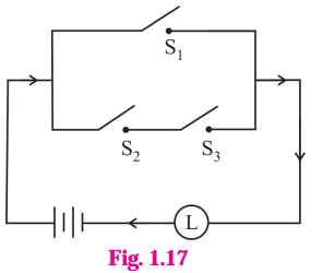
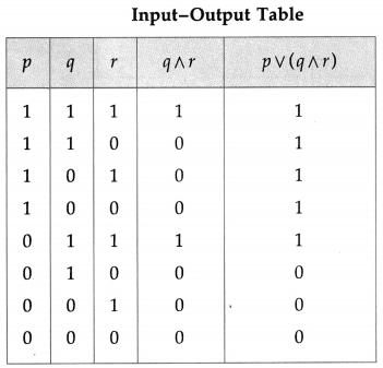
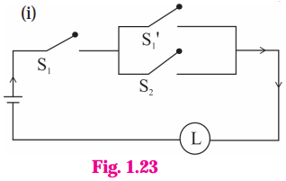
(i) The symbolic form of the given circuit is : p ∨ (q ∧ r) = l
l is generally dropped and it can be expressed as : p ∨ (q ∧ r).
(ii)
Solution:
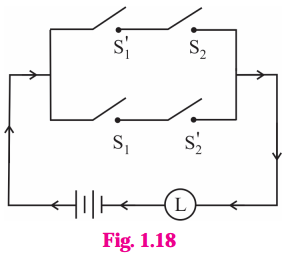
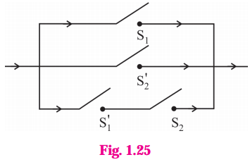
The symbolic form of the given circuit is : (~ p ∧ q) ∨ (p ∧ ~ q).

(iii)
Solution:
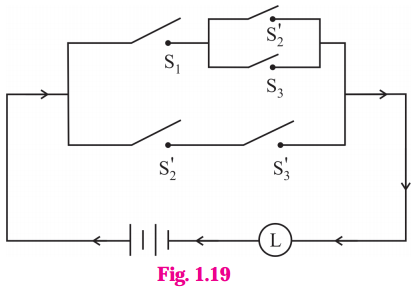
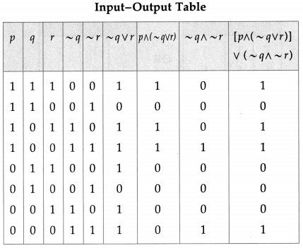
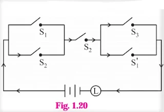
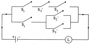
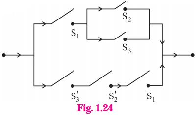
The symbolic form of the given circuit is : [p ∧ (~q ∨ r)] ∨ (~q ∧ ~ r).
(iv)
Solution:
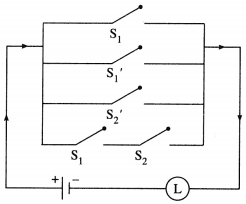
The symbolic form of the given circuit is : (p ∨ q) ∧ q ∧ (r ∨ ~p).

(v)
Solution:
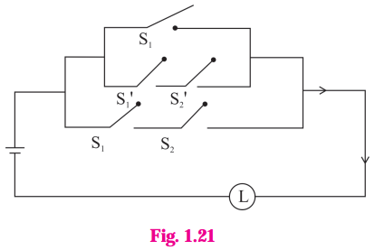
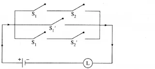
The symbolic form of the given circuit is : [p ∨ (~p ∧ ~q)] ∨ (p ∧ q).
(vi)
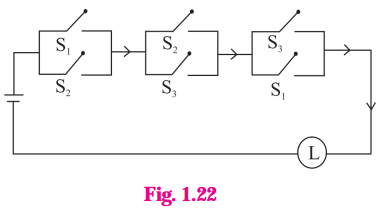
Solution:
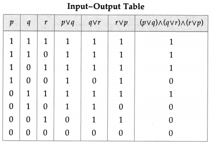
The symbolic form of the given circuit is : (p ∨ q) ∧ (q ∨ r) ∧ (r ∨ p)
Question 2.Construct the switching circuit of the following :
(i) (~p∧ q) ∨ (p∧ ~r)
Solution:
Let p : the switch S1 is closed
q : the switch S2 is closed
r : the switch S3 is closed
~p : the switch S1‘ is closed or the switch S1 is open
~ q : the switch S2‘ is closed or the switch S2 is open
~ r : the switch S3‘ is closed or the switch S3 is open.
Then the switching circuits corresponding to the given statement patterns are :

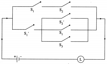
(ii) (p∧ q) ∨ [~p ∧ (~q ∨ p ∨ r)]
Solution:
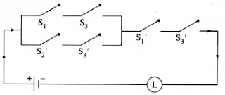
(iii) [(p ∧ r) ∨ (~q ∧ ~r)] ∧ (~p ∧ ~r)
Solution:
(iv) (p ∧ ~q ∧ r) ∨ [p ∧ (~q ∨ ~r)]
Solution:
(v) p ∨ (~p ) ∨ (~q) ∨ (p ∧ q)
Solution:
(vi) (p ∧ q) ∨ (~p) ∨ (p ∧ ~q)
Solution:
Question 3.Give an alternative equivalent simple circuits for the following circuits :
Solution:
(i) Let p : the switch S1 is closed
q : the switch S2 is closed
~ p : the switch S1‘ is closed or the switch Si is open Then the symbolic form of the given circuit is :
p ∧ (~p ∨ q).
Using the laws of logic, we have,
p ∧ (~p ∨ q)
= (p ∧ ~ p) ∨ (p ∧ q) …(By Distributive Law)
= F ∨ (p ∧ q) … (By Complement Law)
= p ∧ q… (By Identity Law)
Hence, the alternative equivalent simple circuit is :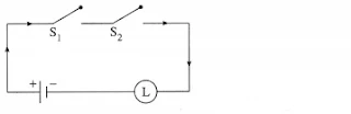
(ii)
Let p : the switch S1 is closed
q : the switch S2 is closed
r : the switch S3 is closed
~q : the switch S2‘ is closed or the switch S2 is open
~r : the switch S3‘ is closed or the switch S3 is open.
Then the symbolic form of the given circuit is :
[p ∧ (q ∨ r)] ∨ (~r ∧ ~q ∧ p).
Using the laws of logic, we have
[p ∧ (q ∨ r)] ∨ (~r ∧ ~q ∧ p)
≡ [p ∧ (q ∨ r)] ∨ [ ~(r ∨ q) ∧ p] …. (By De Morgan’s Law)
≡ [p ∧ (q ∨ r)] ∨ [p ∧ ~(q ∨ r)] … (By Commutative Law)
≡ p ∧ [(q ∨ r) ∨ ~(q ∨ r)) … (By Distributive Law)
≡ p ∧ T … (By Complement Law)
≡ p … (By Identity Law)
Hence, the alternative equivalent simple circuit is :

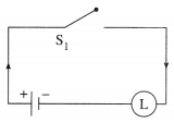
Question 4.Write the symbolic form of the following switching circuits construct its switching table and interpret it.
i)
Solution:
Let p : the switch S1 is closed
q : the switch S2 is closed
~p : the switch S1‘ is closed or the switch S1 is open
~ q : the switch S2‘ is closed or the switch S2 is open.
Then the symbolic form of the given circuit is :
(p ∨ ~q) ∨ (~p ∧ q)

Since the final column contains all’ 1′, the lamp will always glow irrespective of the status of switches.
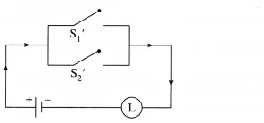
ii)
Solution:
Let p : the switch S1 is closed
q : the switch S2 is closed
~p : the switch S1 is closed or the switch S1 is open.
~q : the switch S2‘ is closed or the switch S2 is open.
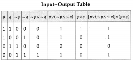
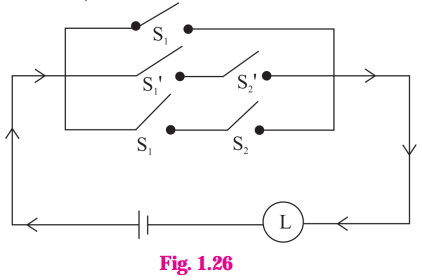
Then the symbolic form of the given circuit is : p ∨ (~p ∧ ~q) ∨ (p ∧ q)
Since the final column contains ‘0’ when p is 0 and q is ‘1’, otherwise it contains ‘1′.
Hence, the lamp will not glow when S1 is OFF and S2 is ON, otherwise the lamp will glow.
iii)

Solution:
Let p : the switch S1 is closed
q : the switch S2 is closed
r : the switch S3 is closed
~q : the switch S2‘ is closed or the switch S2 is open
~r: the switch S3‘ is closed or the switch S3 is open.
Then the symbolic form of the given circuit is : [p ∨ (~q) ∨ r)] ∧ [p ∨ (q ∧ r)]

From the switching table, the ‘final column’ and the column of p are identical. Hence, the lamp will glow which S1 is ‘ON’.
Question 5.Obtain the simple logical expression of the following. Draw the corresponding switching circuit.
(i) p ∨ (q ∧ ~ q)
Solution:
Using the laws of logic, we have, p ∨ (q ∧ ~q)
≡ p ∨ F … (By Complement Law)
≡ p … (By Identity Law)
Hence, the simple logical expression of the given expression is p.
Let p : the switch S1 is closed
Then the corresponding switching circuit is :
(ii) (~p ∧ q) ∨ (~p ∧ ~q) ∨ (p ∧ ~q)]
Solution:
Using the laws of logic, we have,
(~p ∧ q) ∨ (~p ∨ ~q) ∨ (p ∧ ~q)
≡ [~p ∧ (q ∨ ~q)] ∨ (p ∧ ~ q)… (By Distributive Law)
≡ (~p ∧ T) ∨ (p ∧ ~q) … (By Complement Law)
≡ ~p ∨ (p ∧ ~q) … (By Identity Law)
≡ (~p ∨ p) ∧ (~p ∧~q) … (By Distributive Law)
≡ T ∧ (~p ∧ ~q) … (By Complement Law)
≡ ~p ∨ ~q … (By Identity Law)
Hence, the simple logical expression of the given expression is ~ p ∨ ~q.
Let p : the switch S1 is closed
q : the switch S2 is closed
~ p : the switch S1‘ is closed or the switch S1 is open
~ q : the switch S2‘ is closed or the switch S2 is open,
Then the corresponding switching circuit is :
(iii) [p (∨ (~q) ∨ ~r)] ∧ (p ∨ (q ∧ r)
Solution:
Using the laws of logic, we have,
[p ∨ (~ (q) ∨ (~r)] ∧ [p ∨ (q ∧ r)]
= [p ∨ { ~(q ∧ r)}] ∧ [p ∨ (q ∧ r)] … (By De Morgan’s Law)
= p ∨ [~(q ∧ r) ∧ (q ∧ r) ] … (By Distributive Law)
= p ∨ F … (By Complement Law)
= p … (By Identity Law)
Hence, the simple logical expression of the given expression is p.
Let p : the switch S1 is closed
Then the corresponding switching circuit is :
(iv) (p ∧ q ∧ ~p) ∨ (~p ∧ q ∧ r) ∨ (p ∧ ~q ∧ r) ∨ (p ∧ q ∧ r)
Question is Modified
(p ∧ q ∧ ~p) ∨ (~p ∧ q ∧ r)∨ (p ∧ q ∧ r)
Solution:
Using the laws of logic, we have,
(p ∧ q ∧ ~p) ∨ (~p ∧ q ∧ r) ∨ (p ∧ q ∧ r)
= (p ∧ ~p ∧ q) ∨ (~p ∧ q ∧ r) ∨ (p ∧ q ∧ r) … (By Commutative Law)
= (F ∧ q) ∨ (~p ∧ q ∧ r) ∨ (p ∧ q ∧ r) … (By Complement Law)
= F ∨ (~p ∧ q ∧ r) ∨ (p ∧ q ∧ r) … (By Identity Law)
= (~p ∧ q ∧ r) ∨ (p ∧ q ∧ r) … (By Identity Law)
= (~ p ∨ p) ∧ (q ∧ r) … (By Distributive Law)
= T ∧ (q ∧ r) … (By Complement Law)
= q ∧ r … (By Identity Law)
Hence, the simple logical expression of the given expression is q ∧ r.
Let q : the switch S2 is closed
r : the switch S3 is closed.
Then the corresponding switching circuit is :

Mathematical Logic - Ex 1.5 | Maharashtra Board 12th Maths Solutions Chapter 1
Application of Logic to switching circuits :
We shall study how the theory of Logic can be applied in switching network. We mhave seen that a logical statement can be either true or false i.e. it can have truth mvalue either T or F.
A similar situation exists in various electrical devices. For example, an electric switch can be on or off. In 1930 Claude Shannan noticed an analogy between operation of switching circuits and operation of logical connectives. In an electric mcircuit, switches are connected by wires. If the switch is 'on', it allows the electric current to pass through, it. If the switch is 'off', it does not allow the electric current to pass through it. We now define the term 'switch' as follows. Switch : A switch is a two state device used to control the flow of current in a circuit. We shall denote the switches by letters S, S1 , S2 , S3 .... etc.
When the switch S is closed (i.e. on), then current flows in the circuit and hence the lamp glows. When the switch S is open (i.e. off), then current does not flow in the circuit and subsequently the lamp does not glow. The theory of symbolic logic can be used to represent a circuit by a statement pattern. Conversely for given statement pattern a circuit can be constructed. Corresponding to each switch in the cirucit we take a statement letter in statement pattern. Switches having the same state will be denoted by the same letter and called equivalent switches. Switches having opposite states are denoted by S and S'.
They are called complementary switches. In circuit we don't show whether switch is open or closed. corresponds to statement letter p in the corresponding statement pattern.
We write it as p : switch S1
and ~ p : switch S'1
The correspondence between switch S2 and statement letter q is shown as q : switch S2
and
~ q : switch S'2
.
We don't know the actual states of switches in the circuit. We consider all possible combinations of states of all switches in the circuit and prepare a table, called "Input Output table", which is similar to truth table of the corresponding statement pattern.